 SolarInfo
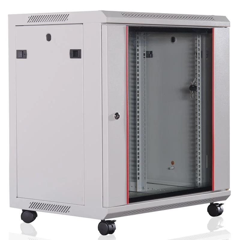
The WDF-C11 is a compact indoor network cabinet platform documented in 4U, 6U, 9U, 12U, 15U and 18U sizes. Each rack height is listed with a 600 mm cabinet width and a choice of 450 mm or 600 mm depth. The platform uses a framed structure, top and bottom cable access, modular front-door options and quick-removal side panels. Wall-mounted and floor-standing arrangements are both referenced in the supplied technical sheet.
This range is intended for smaller communication and network installations where the buyer needs to organize equipment, cabling and accessories in a controlled enclosure without using a full-height data-center cabinet. The correct model still depends on more than rack units. Equipment depth, rear connectors, cable bend radius, heat output, loaded weight and maintenance access must all be checked before a cabinet is ordered.
Where a compact network cabinet fits
The source document describes the cabinet as a general supporting enclosure for network engineering, digital data network projects and multimedia communication systems. Typical compatible equipment may include small communication devices, modems, test instruments, UPS equipment, network servers and compact computer hardware.
That list should be treated as an application guide rather than a universal compatibility statement. A device can fit within the nominal U height and still be unsuitable because its chassis is too deep, its rails need rear mounting points, its cables cannot bend safely or its heat load exceeds the ventilation plan. The equipment manufacturer’s installation requirements remain the controlling reference.
Common use cases for a compact cabinet include:
- Office and branch network distribution
- Telecommunications and structured-cabling termination
- Security, access-control and monitoring equipment
- Small server, gateway and edge-computing installations
- Test, instrumentation and communications support equipment
- Indoor projects where wall space or floor area is limited
WDF-C11 construction at a glance
The WDF-C11 technical sheet specifies a framed cabinet with cable-entry routes at both the top and bottom. This gives the installer more flexibility when the building cable tray is above the cabinet, when cables rise from a floor route or when power and data paths need to enter from different directions.
The front of the cabinet uses a modular door arrangement. The documented choices include a solid steel door, perforated door and glass door. Quick-removal side panels are intended to make installation and maintenance easier. The sheet also refers to wall-mounted and floor-standing installation options.
The source lists square-hole mounting members with a thickness of 1.5 to 2.0 mm and other sheet-metal components with a thickness of 1.0 to 1.2 mm. The cabinet is described as using cold-rolled steel sheet or coil. The material grade, actual thickness of each part and supplier must follow the approved project BOM rather than a general family description.
WDF-C11 size and model table
The supplied ordering guide documents twelve configurations. Each U height has two depth choices.
| Model | Rack height | Width | Depth | Overall height |
|---|---|---|---|---|
| WDF-C11-01 | 4U | 600 mm | 450 mm | 274 mm |
| WDF-C11-02 | 4U | 600 mm | 600 mm | 274 mm |
| WDF-C11-03 | 6U | 600 mm | 450 mm | 363 mm |
| WDF-C11-04 | 6U | 600 mm | 600 mm | 363 mm |
| WDF-C11-05 | 9U | 600 mm | 450 mm | 496 mm |
| WDF-C11-06 | 9U | 600 mm | 600 mm | 496 mm |
| WDF-C11-07 | 12U | 600 mm | 450 mm | 629 mm |
| WDF-C11-08 | 12U | 600 mm | 600 mm | 629 mm |
| WDF-C11-09 | 15U | 600 mm | 450 mm | 762 mm |
| WDF-C11-10 | 15U | 600 mm | 600 mm | 762 mm |
| WDF-C11-11 | 18U | 600 mm | 450 mm | 892 mm |
| WDF-C11-12 | 18U | 600 mm | 600 mm | 892 mm |
The overall dimensions above come from the supplied technical document. Usable internal depth, rail adjustment range, door clearance and wall-to-rail distance are separate values and should be confirmed on the approved drawing.
How to choose between 450 mm and 600 mm depth
A 450 mm cabinet can reduce projection from the wall and preserve space in a corridor, office or compact equipment room. It is generally the better starting point for shallow patch panels, compact switches, fiber termination and similar equipment whose rear connectors and cable bends remain within the usable internal depth.
A 600 mm cabinet provides more space for deeper devices, rear cable management, power accessories and service clearance. It may also make installation easier when several cable bundles enter the enclosure. The extra external depth does not automatically guarantee compatibility with a server or sliding-rail kit; both usable depth and mounting-point geometry must still be checked.
Before choosing either option, record:
- Maximum chassis depth, including brackets and protruding handles
- Rear connector and power-plug depth
- Required cable bend radius
- Front-to-rear rail position and adjustment range
- Door clearance when equipment is installed
- Space required for a PDU, shelf or cable manager
How much rack height should be reserved
Add the rack-unit demand of every item, including patch panels, switches, shelves, power equipment, fan modules and cable-management components. Then reserve space for cable transitions, ventilation and foreseeable expansion. Selecting a cabinet that exactly matches today’s occupied U space often creates a difficult installation and leaves no controlled growth capacity.
A 4U or 6U cabinet may suit a small termination point. A 9U or 12U enclosure gives more flexibility for active equipment and horizontal cable management. The 15U and 18U models provide additional room for mixed devices, accessories or phased expansion while remaining substantially smaller than a full-height rack.
Wall mounting versus floor standing
The technical sheet refers to both wall-mounted and floor-standing installation. The choice should be based on the loaded cabinet rather than the empty enclosure.
For wall mounting, verify the wall structure, bracket or anchor design, fastener spacing, loaded weight and the moment created by cabinet depth. Confirm that the door and side panels can be opened safely after installation. Cable movement, maintenance access and any local building requirements also need review.
For floor standing, confirm the base arrangement, casters or support feet, anti-tip requirements, anchoring and the route used to move the loaded or partially assembled cabinet into position. The source sheet lists a cabinet static-load range of 60 to 100 kg. The rating for the selected model, mounting method and load distribution must be confirmed in the quotation and drawing.
Selecting the front door
Perforated door
A perforated door is normally the first option to review when installed devices rely on front-to-rear airflow. The perforation pattern and open area should be matched to the equipment and room-cooling arrangement.
Glass door
A glass door allows visual inspection and may suit patching, communication or security equipment with a modest heat load. It should not be selected only for appearance. Confirm how heat will leave the cabinet and whether a fan module is required.
Solid steel door
A steel door provides an opaque physical barrier, but the complete ventilation path still needs to be defined. Side, top, bottom or forced-air openings must support the equipment’s thermal requirements.
Door type, lock, hinge direction, opening angle and removal method should appear on the approved configuration. A family-level option list does not mean every door is available for every model without review.
Cable access and internal organization
Top and bottom cable routes are useful only when the internal layout preserves bend radius and service access. Power and data cables should be organized so that technicians can trace and replace a connection without disturbing unrelated equipment. Cable bundles must not block equipment airflow, door closure or the removal of side panels.
The source ordering guide lists optional L-rails, fixed shelves, fan modules, cable managers, a busbar or grounding-bar arrangement, casters and support posts. Each accessory changes the available space, loading or installation method. A shelf needs a confirmed depth and capacity; a fan module needs power and airflow direction; casters change stability and working height.
Indoor environmental and protection limits
The source document lists IP20 protection and the following reference environmental conditions:
- Operating temperature: -5°C to 55°C
- Storage temperature: -20°C to 55°C
- Operating relative humidity: not more than 80% at 30°C
- Storage relative humidity: 90% to 96% at 40°C ±2°C
- Atmospheric pressure: 65 to 110 kPa
These values describe the supplied cabinet document; they do not override the narrower limits of installed switches, UPS units, batteries or other electronic equipment. IP20 is not an outdoor weather rating. Projects exposed to rain, condensation, conductive dust, corrosive atmosphere or uncontrolled public access need a different enclosure and a project-specific protection review.
Surface preparation and finish
The documented finishing sequence includes degreasing, acid cleaning, phosphating and powder coating, with color customization referenced as an option. For a commercial order, confirm the color code, texture, gloss, coating system, required sample, acceptable appearance criteria and any corrosion-test requirement before production.
A general environmental statement about material or coating does not replace current substance declarations, laboratory reports or destination-market compliance documents. Required evidence should be named in the RFQ and confirmed before the order is released.
How to handle standards and test references
The supplied WDF-C11 sheet cites several rack-dimension, enclosure, vibration and grounding references. Some are legacy designations. A current article should not convert those references into a blanket certification claim.
Ask the supplier to identify which standard applies to the quoted configuration, whether the statement is based on design compatibility or completed testing, which model and revision were evaluated, and whether a current report or certificate is available. The destination country, installed equipment and final mounting method may introduce additional requirements.
Information to include in a WDF-C11 cabinet RFQ
- Required rack height: 4U, 6U, 9U, 12U, 15U or 18U
- Preferred cabinet depth: 450 mm or 600 mm
- Complete equipment list and maximum device depth
- Total installed weight and any concentrated shelf load
- Wall-mounted or floor-standing installation
- Front-door type, lock and hinge requirements
- Top or bottom cable entry and cable-bundle size
- Rail, shelf, fan, cable-management and grounding accessories
- Room temperature, dust, humidity and access conditions
- Color, labels, packing, quantity and destination
- Required drawings, standards, test reports and acceptance records
For current projects, buyers can also compare Huijue’s documented HJWA single-section wall-mount cabinet and HJWB swing-out wall-mount cabinet. The current equivalent or replacement for a WDF-C11 configuration must be confirmed by the project team rather than inferred from similar dimensions.
Frequently asked questions
What sizes are listed for the WDF-C11 network cabinet?
The supplied technical sheet lists 4U, 6U, 9U, 12U, 15U and 18U configurations. Each rack height is shown with a 600 mm cabinet width and either 450 mm or 600 mm depth.
Should I choose a 450 mm or 600 mm deep cabinet?
Choose from the actual equipment depth, rear connectors, cable bends, rails and accessories. A 450 mm cabinet reduces external projection, while a 600 mm cabinet gives more internal planning space. Neither depth should be approved without checking usable internal clearance.
Can the WDF-C11 be wall mounted?
The source sheet references wall-mounted and floor-standing installation. Wall mounting must be checked against the selected model, loaded weight, wall construction, anchors and maintenance clearance.
What front doors are available?
The documented modular choices include solid steel, perforated and glass front doors. Availability, ventilation performance, lock and hinge details must be confirmed for the quoted configuration.
What is the WDF-C11 load capacity?
The technical sheet gives a family static-load range of 60 to 100 kg. The applicable value depends on the selected cabinet, installation method and load distribution and must be confirmed in the approved project documents.
Is the WDF-C11 an outdoor cabinet?
No. The source sheet lists IP20 and describes an indoor network enclosure. Outdoor, wet, corrosive or heavy-dust environments require a different protection level and project-specific enclosure selection.
Are accessories included as standard?
Not necessarily. L-rails, fixed shelves, fan modules, cable managers, busbar or grounding hardware, casters and support posts are presented as configurable items. The quotation and BOM determine what is included.
Confirm the equipment before confirming the cabinet
The WDF-C11 technical platform provides a useful compact-cabinet framework: six rack heights, two depths, modular doors, removable side access and flexible cable entry. A reliable selection still begins with the equipment and the site.
Send the device list, required U space, maximum depth, loaded weight, mounting location, cable route, ventilation needs, accessories, quantity and destination through the rack cabinet quotation form. Huijue can then review the requirement against the current server rack and network cabinet range and define the proposed model, drawing and BOM.
Evidence note: Dimensions, construction features, environmental values and option references in this article follow the supplied WDF-C11 technical document. Current model availability, material source, load rating, test scope, standards, accessories and product equivalence must be confirmed in the latest quotation and controlled commercial documents.
